


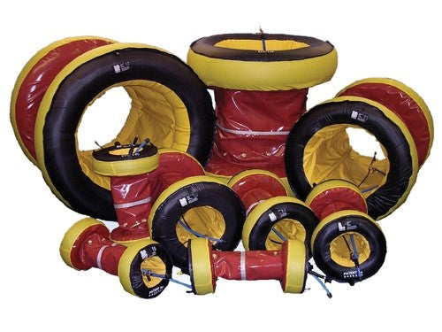
PSQ026 26” Quick-Purge™ System
26” Quick-Purge™ System
PSQ026 26-Inch Quick-Purge™ Inflatable Pipe Weld Purging System
Create a controlled, localized inert-gas purge zone around a 26-inch pipe weld joint. The PSQ026 uses two inflatable dams connected by a short central collar, reducing the volume that must be purged compared with purging an entire pipe section.
The system is designed for weld-purging applications involving stainless steel, Super Duplex, titanium, chromium alloys, nickel alloys and other metals that require controlled protection from oxidation.
Use this product only under an approved welding procedure specification (WPS), manufacturer instructions and the employer’s hot-work, compressed-gas and confined-space safety programs.
Key Features
- 26-inch nominal pipe-purging configuration
- Tandem inflatable dams isolate a localized weld area
- Short central collar minimizes the purge volume
- Designed to reduce purge time and inert-gas consumption
- Integrated pressure-control technology helps protect the bladders from overinflation
- Precision gas-release system distributes purge gas into the weld zone with reduced turbulence
- Luminescent positioning band helps center the system beneath the weld joint
- Primary inflation-and-purge connection
- Auxiliary purge connection or connections for increased purge flow
- Dedicated exhaust or sampling connection for a compatible weld purge monitor
- Designated pull tabs support positioning through longer pipe sections
- Heat-resistant material protects the central collar and dam-edge areas
- Reusable when properly inspected, cleaned, stored and approved for continued service
- Designed for professional pipe fabrication, power generation, petrochemical, pipeline and industrial welding applications
Important Sizing Information
The 26-inch designation identifies the nominal system size. It does not guarantee compatibility with every pipe described as 26 inches.
Before ordering, measure and confirm the actual clear inside diameter of the pipe. Consider:
- Pipe schedule and wall thickness
- Internal coatings or linings
- Weld preparation
- Pipe ovality
- Reducers, valves, branches and internal obstructions
- Available straight length on both sides of the joint
- Bend radius and access route
- Required hose length and connection type
Contact Energy Safety Supply before ordering if the actual pipe inside diameter or installation geometry is uncertain.
How the System Works
The system is positioned with one inflatable dam on each side of the weld joint. When inert purge gas is introduced, the two dams inflate against the pipe’s inside surface and isolate the smaller space between them.
Purge gas then enters the isolated weld zone, displaces the air and exits through the designated exhaust path. A compatible weld purge monitor measures the remaining oxygen.
Once the oxygen concentration reaches the limit required by the approved WPS, welding may begin. Purge-gas flow must continue throughout welding and until the weld has cooled below the material’s oxidation temperature. After the gas is turned off, the system deflates for controlled removal or repositioning.
How to Use the PSQ026
These instructions are a general overview. The current manufacturer manual, approved WPS, work package and site safety procedures control the work.
1. Review the Work Plan
Confirm the pipe material, welding process, acceptable residual-oxygen level, approved purge gas, required flow and pressure, ventilation requirements and cooling criteria.
Do not use the system until the piping has been properly isolated, depressurized, drained, cleaned and declared safe for hot work.
2. Confirm the Pipe Fit and Access Route
Measure the actual clear pipe inside diameter and inspect the path to the weld. Verify that the system can be inserted, positioned, inflated and retrieved without encountering sharp edges, excessive weld penetration, debris, valves or other restrictions.
Do not force the system through an opening or bend.
3. Inspect the System
Before every use, inspect:
- Both inflatable dams
- Central collar
- Dam edges and protective material
- Pull tabs and stitching
- Purge, auxiliary and monitor hoses
- Quick-connect fittings
- Pressure-control and gas-release components
- Luminescent positioning band
Do not use a system with cuts, punctures, abrasion, burned areas, contamination, damaged stitching, loose fittings, blocked hoses or unauthorized repairs.
4. Connect the Hoses
Identify each connection by its label and the manufacturer manual; do not rely only on hose color.
Connect the regulated inert-gas supply to the primary inflation-and-purge inlet. Connect any required auxiliary purge supply and the exhaust or sampling line to a compatible weld purge monitor.
Confirm that every connection is secure and leak-free and that the exhaust path is open.
5. Position the System
Insert the deflated system into the pipe and center the luminescent positioning band beneath the weld-joint opening.
For longer pipe sections, use only the designated pull tabs for positioning. Do not pull the system by its gas or monitor hoses. Pull tabs are not lifting, fall-protection or rigging attachment points.
6. Establish Safe Ventilation
Route displaced air and purge gas to an approved safe location. Argon and other inert gases can displace breathable oxygen without providing a warning odor.
Provide ventilation and atmospheric monitoring as required by the employer’s safety program. Never enter a pipe, vessel or confined space containing purge gas unless all applicable confined-space requirements have been satisfied.
7. Begin Inflation and Purging
Introduce the approved inert gas using the regulator, supply conditions and procedure specified in the manufacturer manual and WPS.
The dams should inflate and seat against the pipe wall before the controlled gas release purges the isolated weld zone. Verify that the system remains centered and stable.
Integrated pressure-control technology helps protect the inflatable dams, but it does not permit the use of an unregulated supply or operation outside the manufacturer’s requirements.
8. Add Auxiliary Purge Gas When Required
For faster purging of the larger isolated volume, use the auxiliary purge connection or connections only as permitted by the operating instructions.
Do not obstruct the exhaust, create uncontrolled pressure within the weld zone or exceed the approved gas-supply conditions.
9. Measure the Oxygen Level
Use a calibrated weld purge monitor capable of accurately measuring the oxygen range required by the WPS.
Do not begin welding based only on elapsed purge time, gas volume, appearance or assumption. The acceptable oxygen concentration depends on the material, process and governing welding specification.
10. Maintain the Purge Through Cooling
Continue the required inert-gas flow throughout welding. Maintain the purge after the arc is extinguished until the weld has cooled below the oxidation temperature specified by the WPS or responsible welding authority.
Stopping the purge too early can allow oxidation while the weld remains hot.
11. Deflate and Remove the System
When the weld has cooled sufficiently, turn off the purge-gas supply and allow the system to deflate.
Remove it using the designated pull tabs without dragging it across sharp or abrasive surfaces. Do not pull it out by the hoses.
12. Inspect and Store
Inspect the system after removal. Remove it from service if it is cut, punctured, burned, abraded, contaminated, distorted or otherwise damaged.
Clean it only by an approved method and store it deflated in a clean, dry location away from sunlight, chemicals, sharp objects and excessive heat.
Published Purge-Time Context
Published product-family benchmarks provide the following approximate times to reach 0.1% oxygen, equivalent to 1,000 ppm:
|
Pipe Diameter |
Published Time to 0.1% Oxygen |
|
24 inches |
6–7 minutes |
|
36 inches |
8–10 minutes |
These times exclude the time required to inflate the dams. A separate verified time is not published for the 26-inch model, so a 26-inch purge time should not be estimated or guaranteed from these figures.
Actual performance depends on fit, leaks, pipe geometry, gas purity, flow, temperature, joint opening and required oxygen level. A published benchmark is not a substitute for measurement with a calibrated weld purge monitor. Additionally, 1,000 ppm is not acceptable for every material or welding procedure.
Use Limitations and Safety Warnings
- Trained personnel must follow the current manufacturer manual and approved WPS.
- Confirm the actual pipe inside diameter before ordering or installation.
- Do not use the system in active, flowing or pressurized piping.
- This product is not a pipe plug, pressure-test plug, flow stopper, mechanical isolation device or personnel-protection device.
- Do not use it to contain liquids, hazardous materials or pressure.
- Never block the purge-gas exhaust path.
- Use a properly regulated, compatible inert-gas supply.
- Never use oxygen, fuel gas or another unapproved gas to inflate or purge the system.
- Secure and handle compressed-gas cylinders under the employer’s compressed-gas program.
- Provide ventilation and atmospheric controls for displaced purge gas.
- Never enter piping or equipment containing an inert-gas atmosphere without an approved confined-space procedure.
- Use a suitable calibrated oxygen monitor; never rely solely on purge time.
- Maintain the purge until the weld has cooled below the applicable oxidation temperature.
- Keep the system away from direct arc exposure, welding spatter, grinding sparks and sharp surfaces.
- Do not pull the system by its hoses.
- Do not use the pull tabs for lifting, rigging, fall protection or personnel support.
- Do not cut, patch, sew, modify or repair the system without written authorization.
- Confirm chemical compatibility before exposing the system to oils, solvents, process residues or cleaning chemicals.
- Remove any damaged, contaminated or improperly functioning system from service.
Temperature Warning
Heat-resistant material is used around the central collar and dam-edge areas. That material capability must not be interpreted as the allowable operating temperature of the complete system.
The standard PSQ026 is not a system for unrestricted preheating, post-weld heat treatment or prolonged elevated-temperature exposure. Hoses, inflatable dams, fittings, stitching and other components may have lower limits than the heat-resistant fabric.
Contact Energy Safety Supply for written application guidance when preheat, elevated interpass temperature or post-weld heat treatment is involved. A purpose-built high-temperature purging system may be required.
From the ESS Team
The three most important parts of using this system are confirming the actual pipe inside diameter, measuring the residual oxygen and maintaining the purge until the weld has cooled sufficiently.
Do not promise or rely on a fixed purge time for the 26-inch model. Published times are family-level examples, and actual conditions can change the result significantly.
Before ordering, provide ESS with the pipe’s actual inside diameter, schedule, material, joint geometry, required oxygen level, approved purge gas, operating temperature, access route, hose requirements and intended welding procedure.
Frequently Asked Questions
Will this fit every 26-inch pipe?
No. Pipe schedule, wall thickness, coatings, ovality and internal restrictions can change the actual inside diameter. Confirm the clear ID before ordering.
What materials can be welded using this system?
It is designed for controlled weld purging of compatible stainless steel, Super Duplex, titanium, chromium alloys, nickel alloys and other materials requiring protection from oxidation. The WPS determines whether the system and purge gas are suitable.
How long will a 26-inch pipe take to purge?
There is no verified 26-inch time published for this model. Published family examples show 6–7 minutes for a 24-inch pipe and 8–10 minutes for a 36-inch pipe to reach 0.1% oxygen, excluding inflation time. Actual oxygen must be measured.
Is 0.1% oxygen low enough to begin welding?
Not necessarily. Although 0.1% equals 1,000 ppm, some materials and procedures require substantially lower oxygen concentrations. The approved WPS and responsible welding authority establish the limit.
Is a weld purge monitor required?
A suitable calibrated monitor should be used whenever the work depends on achieving a specified residual-oxygen concentration. Time alone cannot identify leaks, contaminated gas, turbulence or insufficient purging.
What gas should be used?
Use only the compatible inert purge gas specified by the WPS and manufacturer instructions. Argon is commonly used, but gas selection depends on the material and welding process.
Can the system be overinflated?
The integrated pressure-control feature is designed to protect the dams from overinflation. It does not authorize an unregulated gas supply, unlimited upstream pressure or operation outside the manufacturer’s instructions.
Can it be used during preheating or post-weld heat treatment?
Do not assume so. The standard PSQ026 is not a dedicated high-temperature purging system. Obtain written application guidance before exposure to preheat, elevated interpass temperatures or post-weld heat treatment.
Can the system travel through a pipe bend?
The design supports controlled positioning through suitable pipework, but success depends on the bend radius, pipe ID, obstructions and access. Confirm the exact geometry before attempting to pull it through a bend.
Can the system be reused?
Yes, when reuse is allowed by the work procedure and the system remains clean, functional and undamaged after inspection. Remove damaged or contaminated equipment from service.
Are the purge monitor, regulator and supply hoses included?
Included equipment can vary by the quoted package. Review the ESS order confirmation for the exact hose configuration, fittings, regulator, monitor and accessories supplied.
Can it be used as a pressure plug or flow stopper?
No. This is a low-pressure weld-purging system and must not be used for pressure retention, flow control, pipe isolation or personnel protection.
Documentation
Operating instructions, dimensional information, connection requirements, inspection guidance and available product documentation can be requested through Energy Safety Supply.
The current manufacturer manual and order-specific documentation control over this general product-page summary.